Assembly
RC Binding, Wiring and Software Configuration
- Binding The Receiver and Transmitter
- Changing Connector Types
- Putting it all together
- Configuring the Navio2 and Raspberry Pi
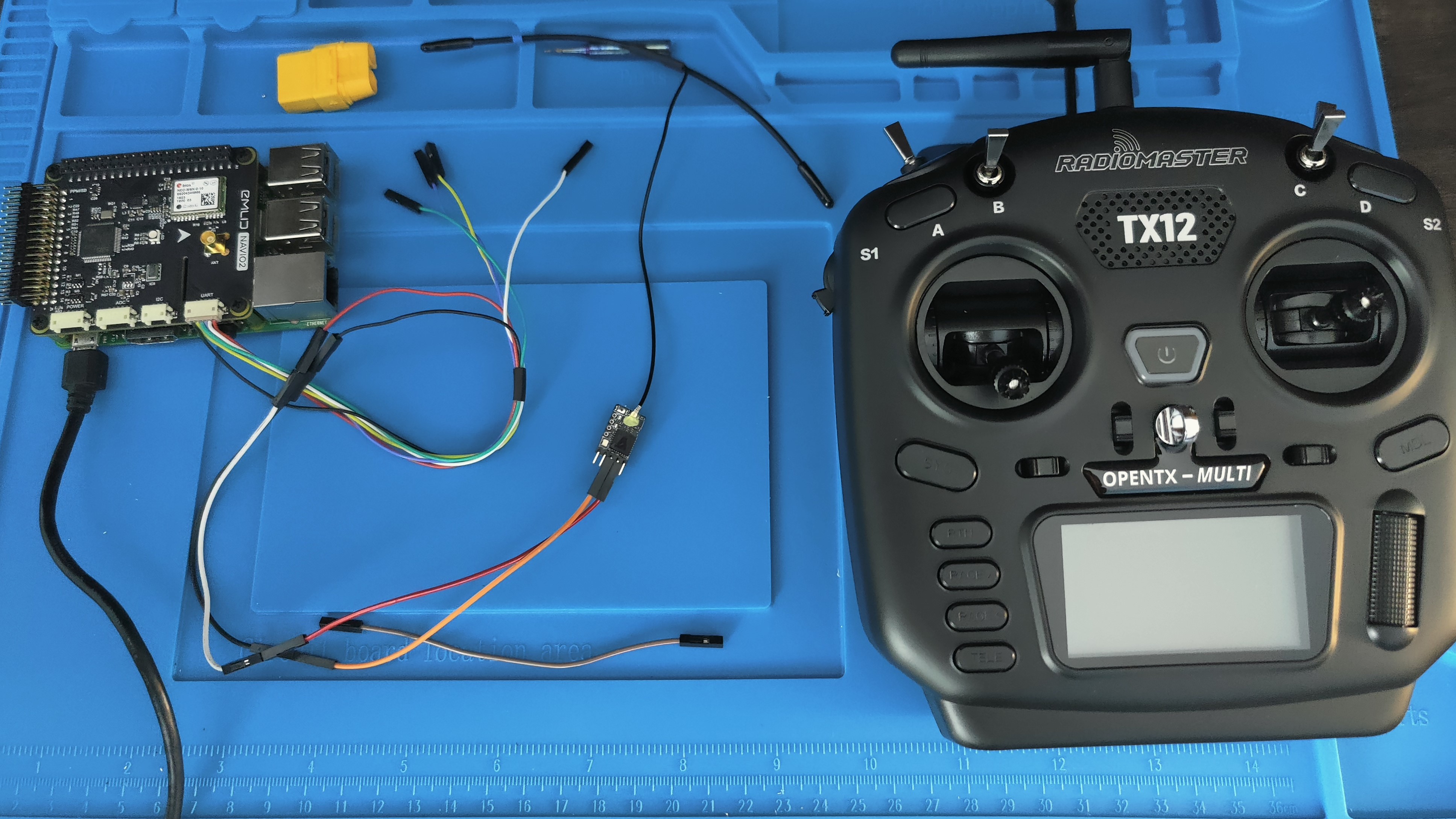
Binding The Receiver and Transmitter
Remember to bind your RC components before installation since you may need to press a small button on your Receiver.
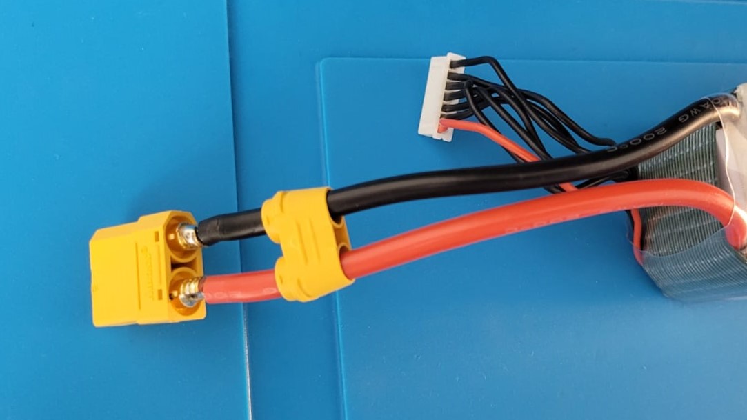
Changing Connector Types
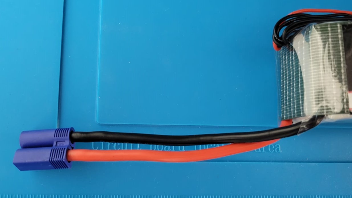
If your battery has an existing connector on it, open the housing at the tail of the connector it should bend/ snap off as shown in the picture below. This should expose the soldering done on both terminals
Do NOT short the battery by mistake. Pliers can conduct electricity so if you want to be even more careful we recommend putting electrical tape over the nose of the pliers!
Our first task is to cover one of the exposed terminals with insulation tape so we accidentally don’t short out the battery
Now heat the solder on the chosen terminal until it melts. As soon as it melts pull the connector so the wire disconnects
Ensure your soldering iron is on its highest setting. Use of a large solder tip is also required so maximum heat can be applied to the quickly disconnect the old connector
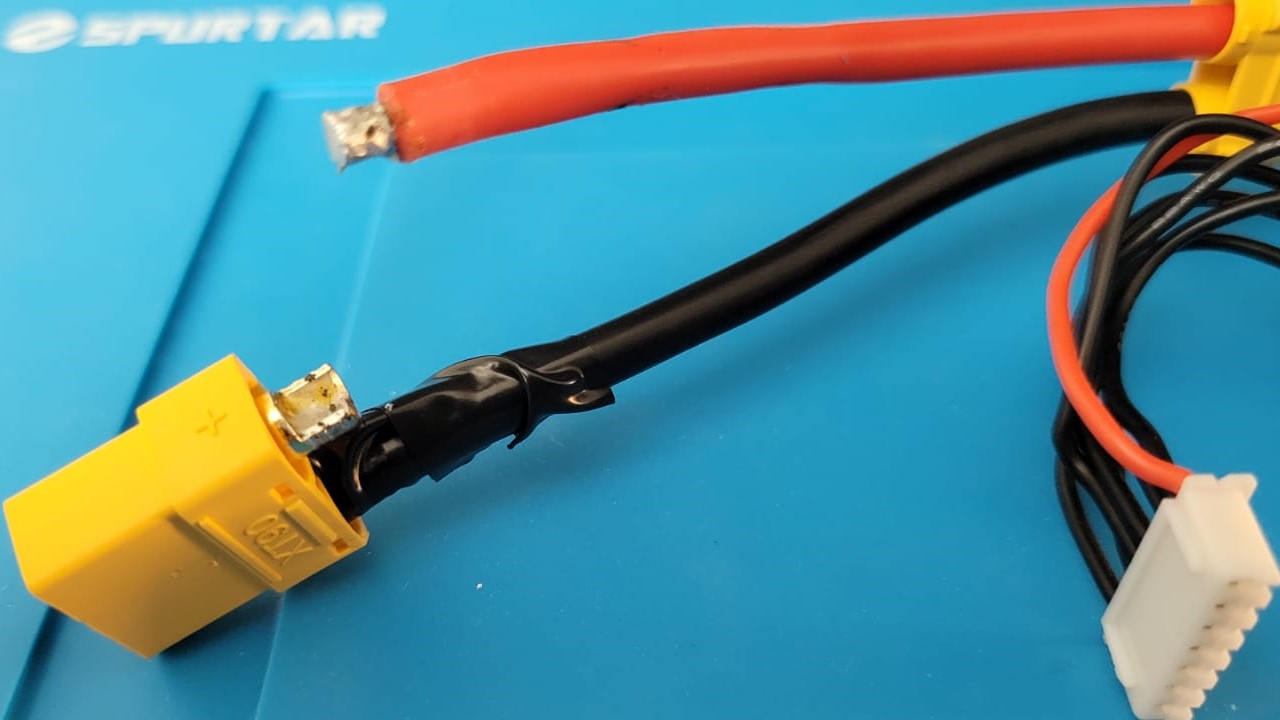
Let the wire cool and cover the exposed wire with insulation tape
Remove the insulation on the other side and repeat this process
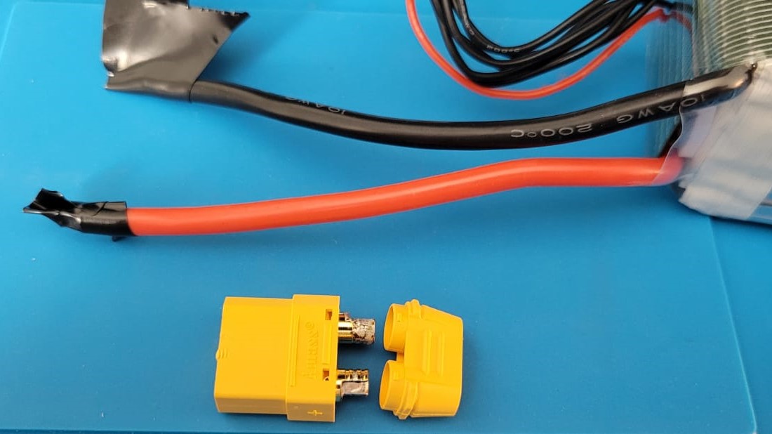
Once the terminal wires are separated from the old connector ensure that both wires are completely insulated
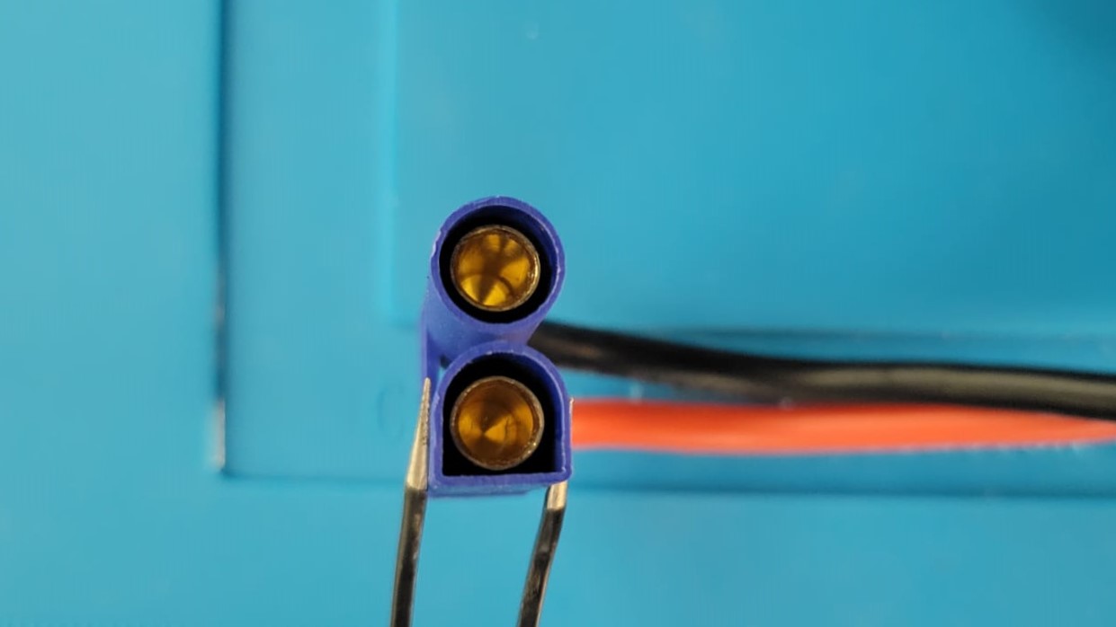
Female connectors are generally used on anything that outputs power
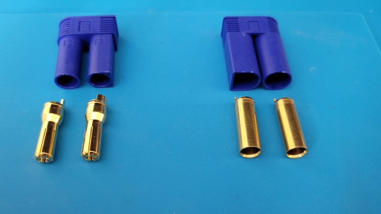
The male connector is on the left and the female is on the right in both images
Slip on the new plastic housing over the wires
Heat the soldering iron to its hottest setting again. Take the bullet connector and heat it by touching the iron to it. Once it is hot enough, melt solder into the small housing at the end of the bullet connector
Remove the insulation from one of the terminals and ensure that it has solder on. Again heat the bullet connector while this time also heating the wire. Ensuring that the bullet connector and wire dont join just yet
Wait for about 10-15 seconds even after the solder has completely melted on both sides. Especially if your irons max temperature is 450°C
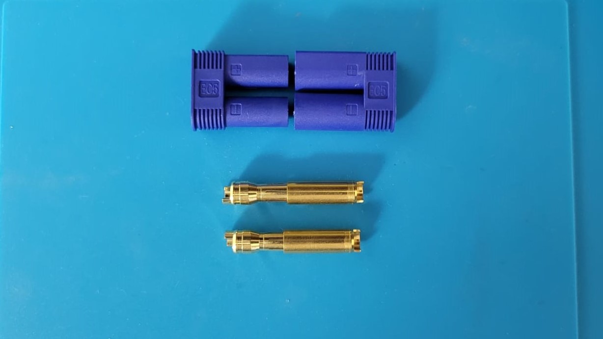
Once you are confident that both sides are hot enough, put the wire into the connector as straight as possible. Redo the process if its not gone in straight. Once you are done it should look like this
After the connector has cooled insulate the terminal completely and repeat the process on the other terminal
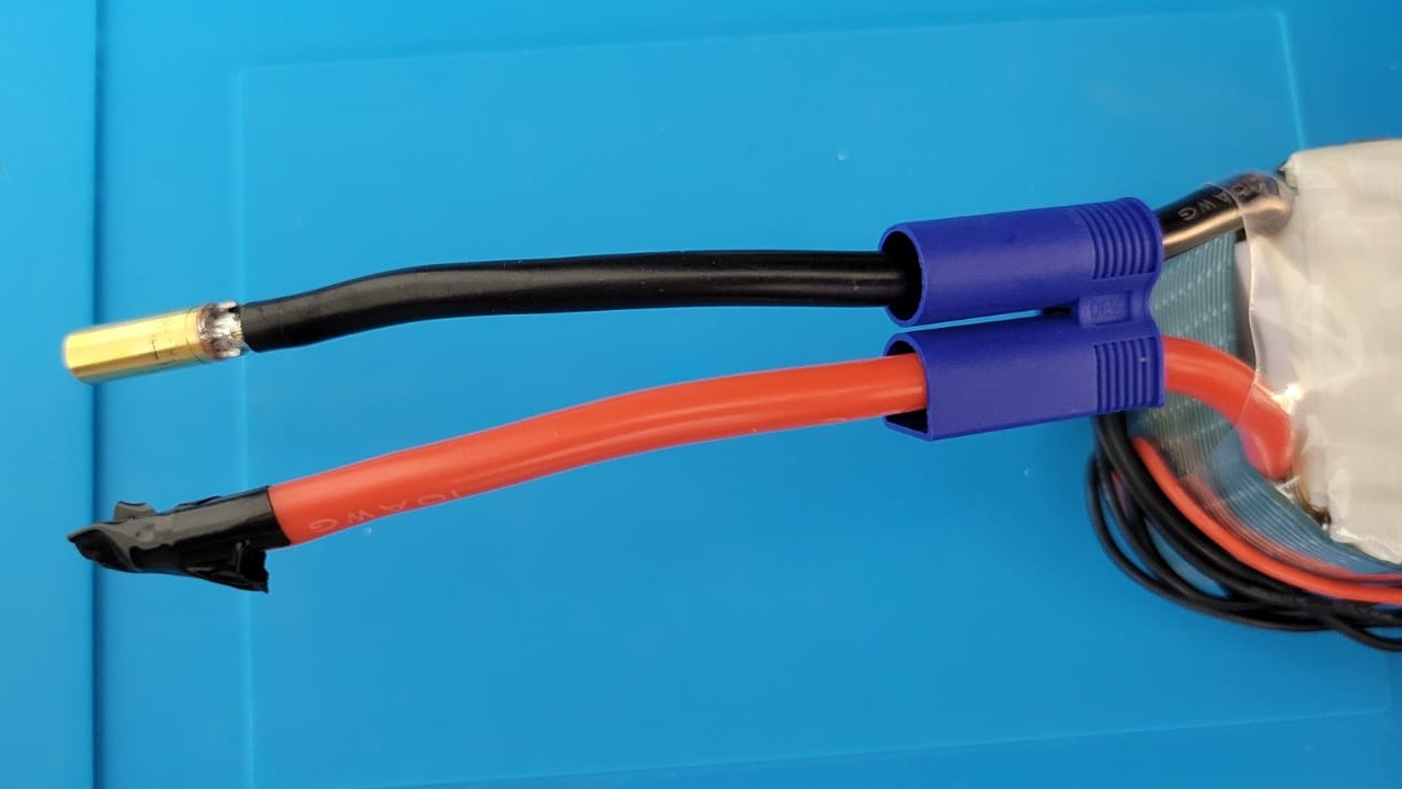
Once you are done with both sides, remove the insulation on ONE terminal and push it into the plastic housing. Remove the other side’s insulation and then carefully place it into the plastic connector as well.
Insulate the plastic terminal you aren’t working on with some electric tape.
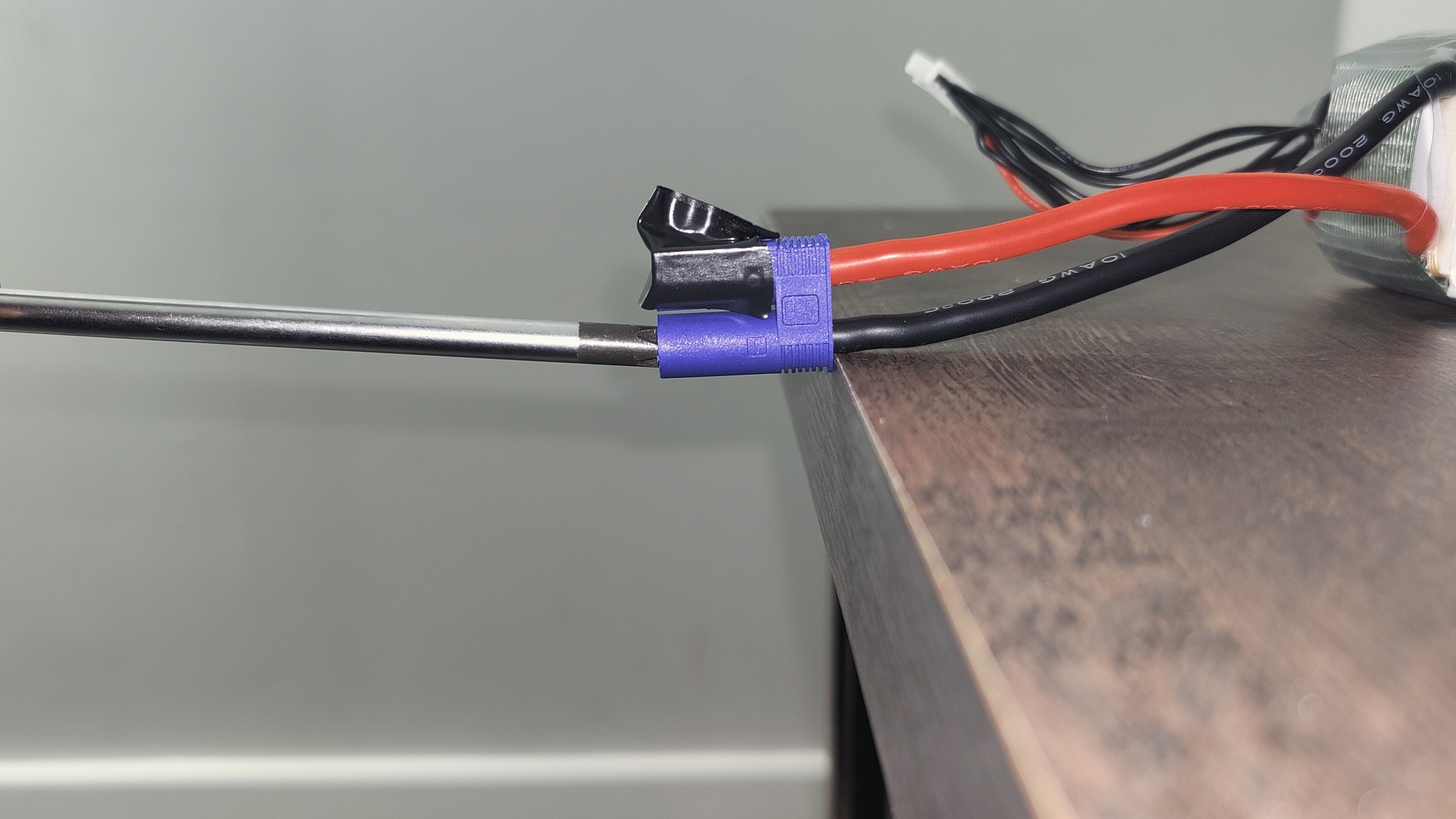
This step will need a lot of force! Use a phillips head screwdriver to push the connector in. The easiest way we found was to put the edge of the connector on an edge of a table, hold the connector and push hard. Here is a picture to help:
After you hear an audible thump on one side remove the other side’s insulation and put it on the completed terminal. Repeat the step again.
Once both sides are done that’s it you have successfully completed the process
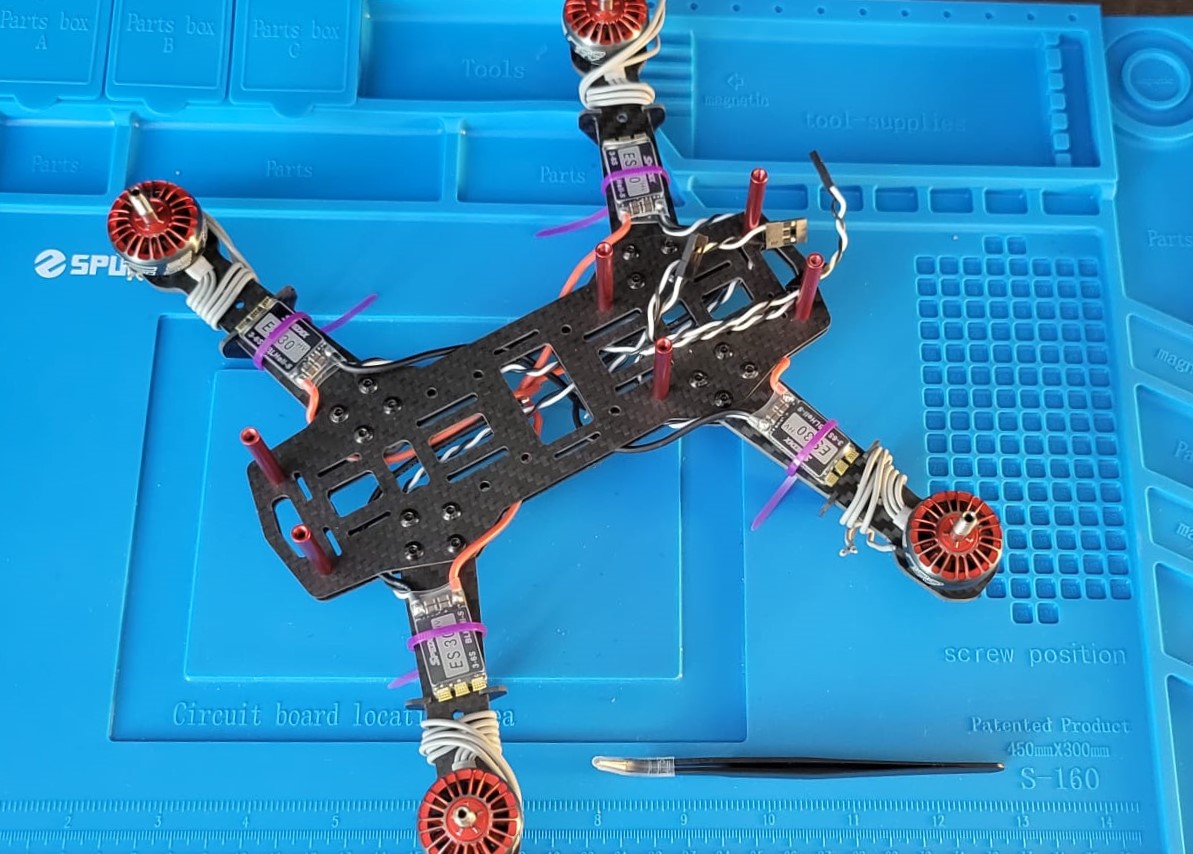
Putting it all together
Start by first placing insulating tape on your drone. This should be in areas where your flight controller and transmitter are housed. Map out how to pass your wires. After passing them, solder the wires and remember to use heat shrink tubing. Each frame is unique but in our case, we used the gap in between the top and bottom of the drone frame.
A pair of tweezers was very useful here!
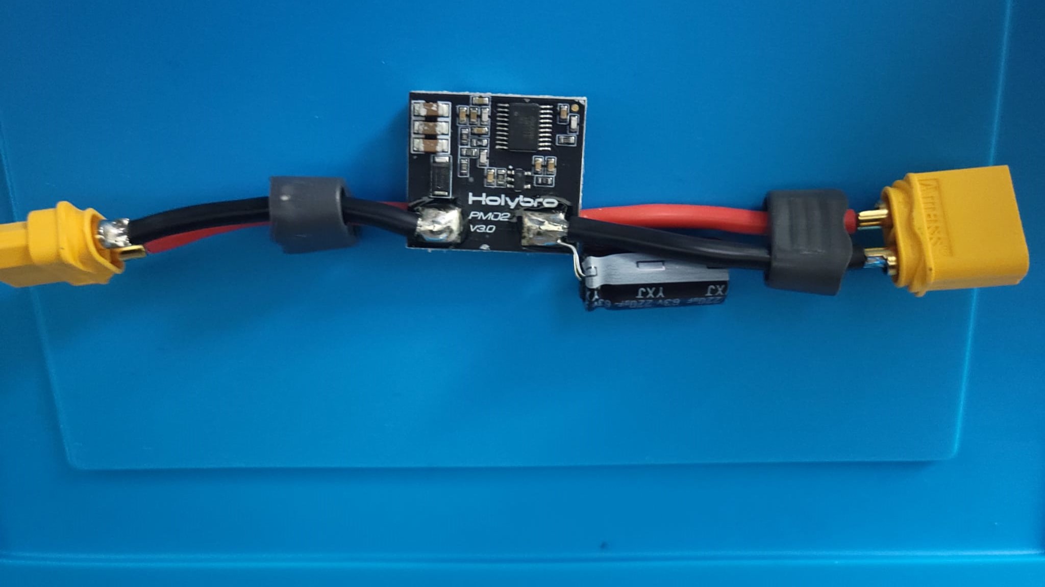
Place your power distribution board (if you are using one) and then solder the main two terminals to the board
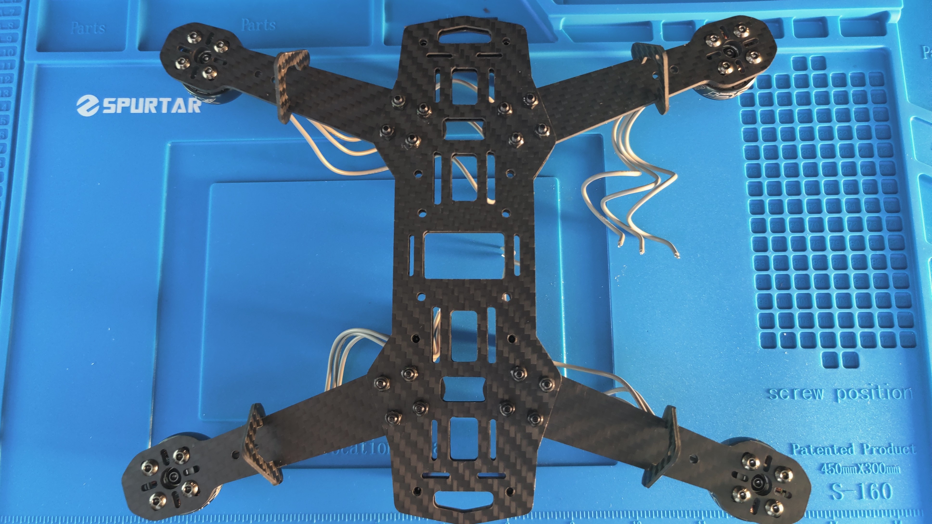
Fasten your ESCs with a bit of double-sided tape and small zip ties for even more security
Connect and solder up all the connections from the motors to the ESCs
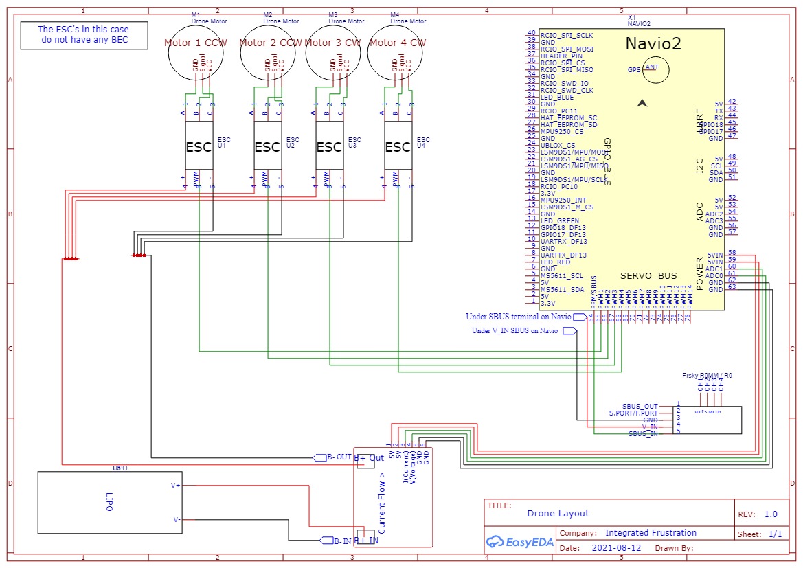
Securely place your flight controller in place by using zip ties or strong velcro straps. We used the following wiring setup:
Lastly secure the battery in such a way that the load is balanced in the center
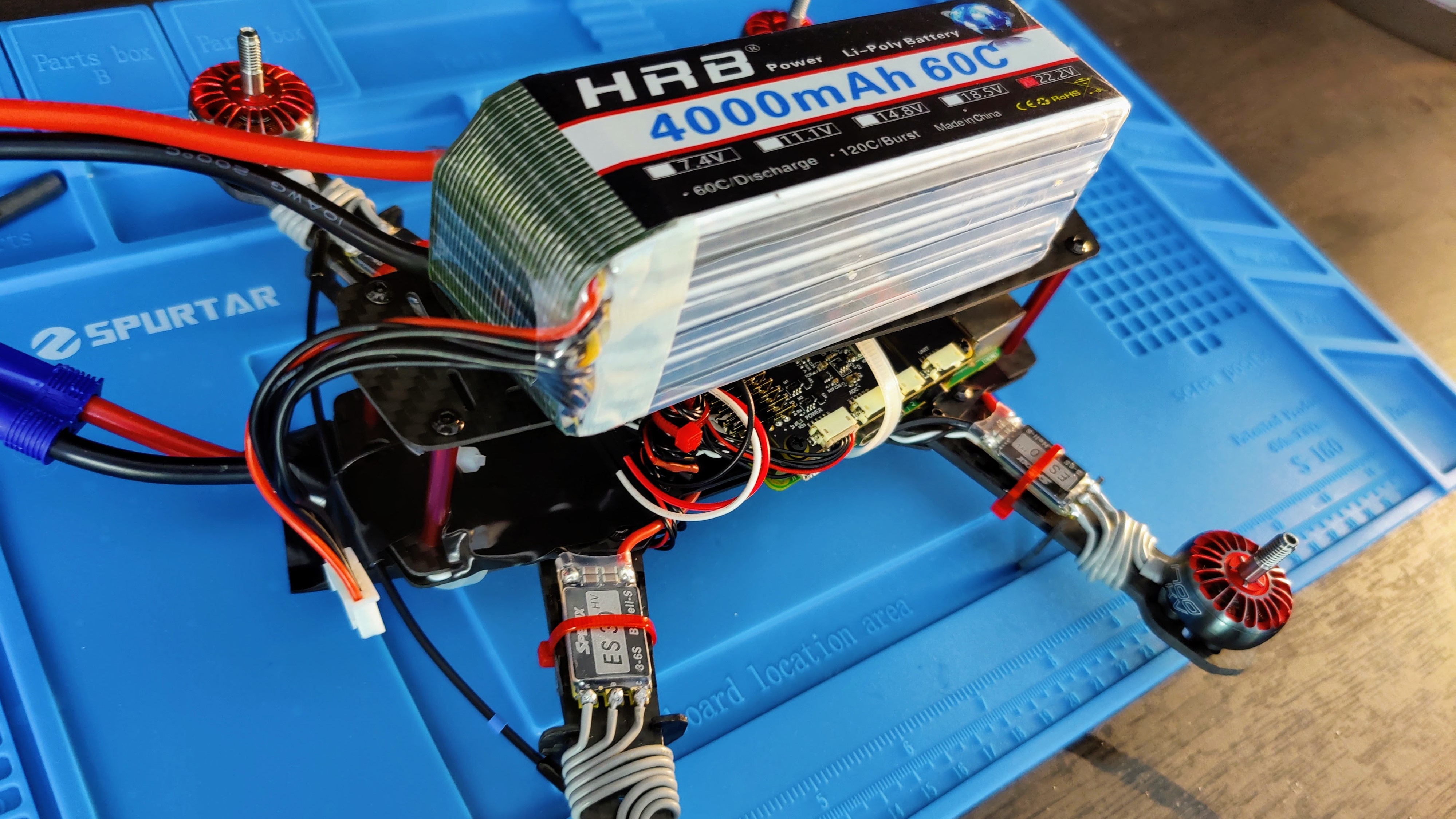
Connect your transmitter and then power on your already bounded receiver by connecting the battery on the drone
Configuring the Navio2 and Raspberry Pi
This was a suprisingly easy process! Follow the steps on Emlid’s documentation to setup the firmware and then your drone should be ready for calibration and…
…Ready for Flight!