Assembly
Overview of the Arduino bootloader and soldering process
The Assembly Plan!
We suggest preparing all the components needed before starting the project. This includes preparing the header pins.
Get a breadboard out! It’s time to burn the bootloader on the chip! We recommend doing this separately and not once the board is fully prepared because it’s easy to differentiate between any chip issues or board soldering mistakes. If you have an existing Arduino board this process is straightforward.
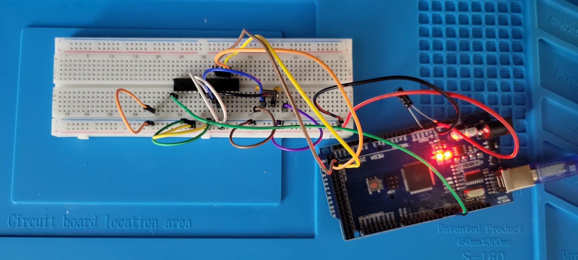
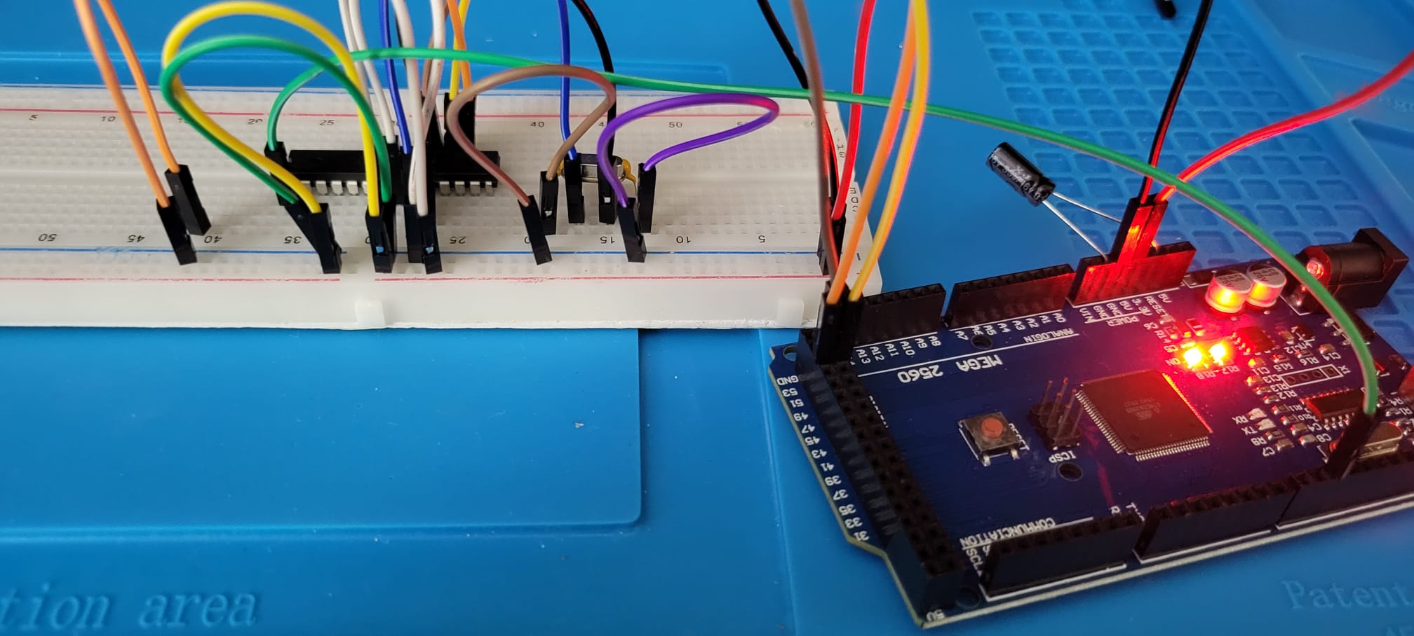
If you have a MEGA Arduino board the process could not be explained better than here. We would like to take this opportunity to thank Eng. Shady Mohsen for his extremely clear explanation of the whole process. We are very grateful to have stumbled on the blog with all its interesting demos and projects!
Once the burning of the bootloader happens successfully (as shown in the GIF below) from the Arduino IDE, we recommend testing the board by uploading the blink sketch to the microcontroller.
After the blink sketch is uploaded connect a LED with a resistor (~270 ohms) to pin 19 of the ATMEGA328P-PU chip and ground. You should see the iconic blinking LED that we see when buying any new Arduino board.
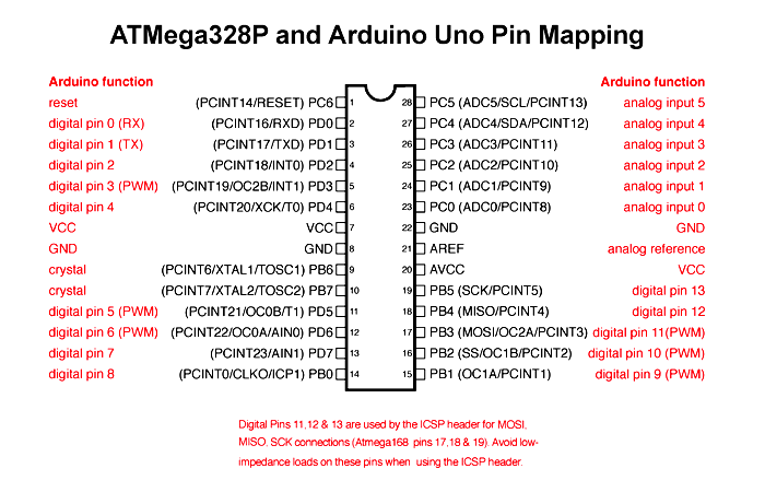
Credit: Components101
Next it’s time to solder all our components on the PCB as shown below. If in doubt about what’s where please have a look at the Circuit Construction and Generation page.
Start from small to big. It’s very important to start soldering the smallest components, in this case the resistors. This will ensure components are inserted straight. For some tips on soldering the PCB see the following video.
Once you have soldered everything and let the board cool, insert the ATMEGA328P-PU chip and the Arduino board should be good to go!
At this point you can use the FTDI FT232RL to program any Arduino Uno sketch on the board!